Commercial LED lighting rarely fails for one dramatic reason. More often, several small stresses accumulate inside the driver. Heat, voltage surges, moisture, incompatible controls, and poor thermal design can shorten service life. The U.S. Department of Energy’s LED Luminaire Lifetime: Recommendations for Testing and Reporting identifies driver electronics as a major factor in overall luminaire reliability. The report also stresses that rated LED life does not automatically represent complete system life.
So, what causes commercial led drivers to fail? Field experience points to thermal stress as a frequent contributor. A driver mounted above a hot ceiling may operate beside insulation, dust, and limited airflow. Internal temperatures can rise quietly. Electrolytic capacitors then dry out faster, especially when ripple current remains high. DOE solid-state lighting research has repeatedly connected temperature management with component reliability. NEMA guidance on LED drivers also highlights the need to match electrical ratings, controls, and operating conditions carefully.
Surge events create another practical threat. A parking-lot fixture may face repeated switching, lightning-related transients, or unstable supply conditions. Poor grounding can make the problem worse. Dimming systems can introduce stress when drivers lack proper compatibility. Moisture enters through damaged seals or badly positioned cable glands. Sometimes, the real cause is installation quality, not the driver itself.
These conclusions are useful, but not absolute. Manufacturer lifetime claims often depend on controlled test conditions. Commercial buildings are messier. The 2023 U.S. DOE Solid-State Lighting R&D Opportunities report continues to emphasize reliability testing, thermal control, and system-level design. This article examines the leading 2026 failure causes, using technical evidence, field observations, and the limits of published data.
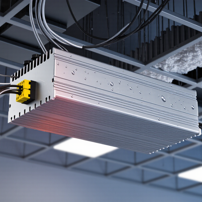
A commercial LED driver is the control center between building power and the LED light source. It converts incoming AC power into controlled DC current. This keeps LED output stable and prevents excessive current from damaging the light engine. Many drivers also manage dimming, startup behavior, surge protection, and thermal limits.
In commercial sites, driver failure often begins with heat. A driver trapped above a hot ceiling can operate beyond its rated temperature for months. Poor ventilation, loose wiring, voltage fluctuations, moisture, and repeated switching add stress. During inspections, technicians should check terminal tightness, enclosure temperature, burn marks, and output current. A flickering fixture is not always a bad LED module. The driver may be reacting to an incompatible dimming signal or weakening internal components.
Installation details matter more than many project schedules allow. The driver must match the LED load, input voltage, dimming method, and operating environment. One mistake I still see is treating wattage as the only matching requirement. That shortcut can create unstable lighting and premature failure. However, not every failure is easy to diagnose on site. Dust, hidden heat, and aging power infrastructure can overlap. Recording operating temperature and maintenance history provides more reliable evidence than replacing parts by guesswork. Fresh measurements help.
Commercial LED driver failure in 2026 will often begin with excessive heat, not sudden electrical overload. In maintenance inspections, hot enclosures, darkened circuit boards, and brittle insulation reveal the pattern. Every extra degree stresses capacitors, switching devices, and solder joints. The driver may continue operating for months. Then output flickers or shuts down. Heat leaves evidence.
Poor thermal management usually combines several small mistakes. A sealed housing can trap warm air around the driver. An undersized heat sink slows heat transfer. Dust on vents adds another insulating layer. Thermal pads may also be compressed unevenly, leaving tiny air gaps. These gaps matter because air transfers heat poorly.
Ambient temperature matters too. A driver rated for 25°C conditions may struggle inside a roof-level fixture at 45°C. Designers should verify case temperature, airflow, load current, and junction-temperature limits under realistic conditions. Infrared checks and data logging can expose peaks that a brief bench test misses.
The repair is not always a larger heat sink. Reducing output current, improving contact pressure, separating heat sources, or adding controlled ventilation may work better. During audits, I would record temperatures after several hours, not only at startup. A cool first reading proves little. Engineers should also review capacitor temperature ratings and derating curves.
I have seen acceptable calculations fail in dusty, enclosed installations. That is a useful warning: thermal design needs field feedback, not assumptions. Some failures remain difficult to isolate when airflow changes with seasons or cleaning schedules.
Voltage surges and unstable power remain serious threats to commercial LED drivers. A brief surge can punch through input protection, while repeated brownouts stress switching components and electrolytic capacitors. Heat makes the damage worse.
Uptime Institute’s 2024 Annual Outage Analysis reported power-related events in about 54% of significant data-center outages. Commercial lighting systems face smaller events, but the mechanism is similar. Loose neutral connections, overloaded circuits, generator transfers, and nearby motor starts can create damaging voltage changes. IEEE 1159 identifies sags, swells, interruptions, and transients as distinct power-quality events. A driver may survive one event, then fail weeks later. That delay often misleads maintenance teams.
A useful warning: not every early failure means the driver was defective. Poor grounding, undersized surge protection, or high ambient temperature may be the real cause. I have seen installations where replacing drivers solved symptoms briefly, but the unstable feeder remained untouched. That is an expensive lesson.
Tips: Measure the circuit with a power-quality analyzer, not only a handheld multimeter. Check neutral tightness, grounding continuity, and peak transient levels. Install correctly rated surge protective devices at the panel and lighting circuit. Keep drivers below their rated case temperature, especially above ceiling spaces. Record failure dates and operating conditions. Patterns matter. Recheck the assumptions.
How Moisture, Dust, and Harsh Environments Accelerate Failure
In field inspections, moisture is often the quietest cause of LED driver failure. It enters through cable glands, cracked seals, or pressure changes during cooling. Condensation can form inside a warm fixture after nighttime temperature drops. Repeated wet-dry cycles corrode terminals and weaken insulation. Not immediately. Months of repetition can destroy reliability, especially in parking structures, food-processing areas, and outdoor walkways.
Dust creates a different problem. Fine particles settle on heat sinks and circuit boards, restricting airflow and trapping heat. Dust mixed with humidity may form conductive deposits across sensitive components. In workshops or warehouses, airborne fibers can collect around vents and connectors. A clean exterior can mislead. Internal contamination may already be raising operating temperatures beyond the driver’s design range.
Harsh environments add continuous stress through heat, salt air, chemical vapor, and vibration. Thermal cycling expands and contracts solder joints, while vibration can loosen terminals over time. I have seen maintenance teams check light output but ignore internal humidity and driver temperature. That gap matters. Properly rated enclosures, secure cable entries, and suitable drainage reduce exposure. Thermal measurements under actual load reveal more than a visual inspection. Maintenance records should note condensation, dust buildup, abnormal noise, and repeated resets. Some failures still occur despite good installation, which makes environmental monitoring worth reviewing.
2026 Top Causes of Commercial LED Driver Failure?
Commercial LED driver failure rarely comes from one dramatic event. In 2026, common causes remain capacitor aging, thermal stress, design limits, and installation mistakes. Electrolytic capacitors gradually lose capacitance as heat dries their electrolyte. That increases ripple current and can create flicker, dimming, or sudden shutdowns. Repeated hot-cold cycles also weaken solder joints and transformer insulation. Heat is often the quietest threat. An enclosed ceiling, blocked ventilation, or a driver mounted beside a hot luminaire can push internal temperatures beyond its rating. Field inspections show that a clean installation can still hide poor airflow.
Design margins matter. A driver operating near its maximum current has little tolerance for voltage surges, high ambient temperatures, or LED module variation. Undersized components may pass factory testing but fail after thousands of operating hours. Installation errors accelerate this process. Loose terminals create resistance and heat. Incorrect wiring can damage input stages. Unsuitable dimming controls may produce unstable output. Small details become expensive. Still, temperature alone does not explain every failure. Service histories are often incomplete, so conclusions require careful testing.
Tips: Measure case temperature after several operating hours, not immediately after startup. Check airflow, terminal torque, input voltage, and ripple current. Leave thermal clearance around the housing. Replace visibly swollen capacitors promptly. Record failure conditions, because memory is less reliable than measurements.
| Rank | Failure Cause | Primary Stress Mechanism | Typical Field Symptoms | Components Most at Risk | Design or Installation Warning Signs | Recommended Prevention | Relative Risk |
|---|---|---|---|---|---|---|---|
| 1 | Excessive Operating Temperature | Higher temperature accelerates chemical, electrical, and mechanical aging. Electrolytic capacitor life commonly decreases as core temperature rises; a widely used engineering rule is that life approximately doubles for each 10 °C reduction within the component’s rated range. | Intermittent shutdown, output flicker, reduced light level, discoloration, or complete loss of output after warm-up. | Electrolytic capacitors, power semiconductors, transformers, optocouplers, solder joints, and thermal-interface materials. | Small enclosure, blocked ventilation, high ambient temperature, inadequate heat sinking, or a driver case temperature close to its maximum rating. | Provide thermal derating, improve airflow and heat transfer, keep the driver away from heat sources, and verify the in-situ case temperature under worst-case load. | High |
| 2 | Electrolytic Capacitor Aging and Dry-Out | Electrolyte evaporation, ripple-current heating, seal degradation, and dielectric wear increase equivalent series resistance and reduce capacitance over time. | Increased ripple, audible noise, unstable output current, delayed startup, flicker, or blown input protection. | Bulk DC-link capacitors and secondary-side smoothing capacitors. | High ripple current, high internal temperature, insufficient voltage margin, or a capacitor life rating that does not match the required operating hours. | Use long-life capacitors with appropriate ripple-current and voltage ratings, reduce thermal stress, and validate capacitor life using the actual temperature profile. | High |
| 3 | Input Surge, Lightning, and Transient Events | Short-duration overvoltage creates high current through surge-protection and switching components, causing cumulative degradation or immediate breakdown. | Sudden no-output condition, tripped protection, visible component damage, or failure after a storm or switching event. | MOVs, TVS devices, bridge rectifiers, fuses, switching MOSFETs, and control ICs. | Long outdoor cable runs, exposed building locations, weak protective-earth arrangements, repeated utility disturbances, or insufficient surge coordination. | Coordinate fuses, MOVs, TVS devices, filters, and external surge protective devices; follow the applicable installation code and conduct surge testing appropriate to the site. | High |
| 4 | Output Overload or Incorrect LED Load | Operating beyond the rated output voltage, current, power, or control range increases semiconductor and magnetic-component stress and may trigger repeated protection cycles. | Flicker, automatic restart, reduced output, audible clicking, overheating, or a driver that works only with a specific load. | Power switches, inductors, transformers, current-sense resistors, rectifiers, and output capacitors. | LED modules connected in the wrong series or parallel arrangement, excessive total wattage, incompatible constant-voltage/constant-current pairing, or unstable dimming behavior. | Match the driver to the LED load’s current, voltage, wattage, polarity, and dimming requirements; allow operating margin and test the complete load rather than the driver alone. | High |
| 5 | Moisture, Condensation, and Contamination | Water and ionic contamination reduce insulation resistance, promote corrosion, and can create conductive paths or electrochemical migration across the circuit board. | Intermittent operation, corrosion, nuisance tripping, flicker during humid weather, or progressive insulation failure. | Printed circuit boards, connectors, terminals, optocouplers, transformers, and conformal-coating interfaces. | Condensation inside the enclosure, damaged gaskets, unsealed cable entries, pressure equalization problems, or an enclosure rating unsuitable for the environment. | Use a correctly rated enclosure, sealed cable glands, suitable conformal protection where appropriate, drainage or pressure equalization, and moisture testing during installation qualification. | High |
| 6 | Poor Electrical Connections and Installation Errors | Loose terminals, inadequate torque, damaged conductors, reversed polarity, or mixed wiring create contact resistance, local heating, arcing, and intermittent operation. | Localized heat marks, flicker when wiring is moved, intermittent shutdown, burned terminals, or repeated fuse operation. | Terminal blocks, connectors, wire crimps, solder joints, and input/output conductors. | Loose screws, unsupported cable weight, incorrect wire gauge, insufficient stripping length, stranded wire without suitable ferrules, or failure to follow torque specifications. | Use the specified conductor size and termination method, apply the manufacturer’s torque values, provide strain relief, verify polarity, and perform a final pull and thermal inspection. | High |
| 7 | Voltage, Frequency, and Power-Quality Mismatch | Input conditions outside the driver’s rating increase rectifier, switching, filtering, and control-loop stress. Repeated brownouts can also cause thermal and electrical cycling. | Flicker, audible buzz, premature shutdown, overheating, or failure concentrated on unstable circuits. | Input capacitors, rectifiers, switching devices, control ICs, and power-factor-correction components. | Incorrect supply voltage or frequency, severe voltage dips, harmonic distortion, generator operation, or shared circuits with large inductive loads. | Measure the actual supply at the driver terminals, select the correct input range, separate heavily disturbed loads where practical, and verify operation during expected brownout and recovery conditions. | High |
| 8 | Thermal Cycling and Mechanical Fatigue | Repeated expansion and contraction produce fatigue in solder joints, component leads, board interfaces, and wire connections. | Temperature-dependent intermittent faults, startup failures, visible cracked solder joints, or failure after repeated on/off cycles. | Large capacitors, power semiconductors, transformers, resistors, solder joints, and board-to-wire connections. | Large temperature swings, high switching frequency of the lighting system, rigid mounting, heavy components without support, or insufficient board strain relief. | Limit unnecessary cycling, support heavy components, improve mechanical fixation, use suitable solder-joint design, and test the assembly with representative thermal-cycle profiles. | Medium |
| 9 | Dimming and Control Incompatibility | Incompatible phase-cut dimmers, 0–10 V controls, DALI controls, PWM systems, or auxiliary control wiring can cause unstable control-loop operation and excess stress. | Visible flicker, limited dimming range, dropout at low levels, humming, random restart, or control failure. | Control ICs, input filters, optocouplers, auxiliary power supplies, and switching devices. | Control protocol mismatch, control wires routed with noisy power conductors, control input exceeding its rated range, or minimum-load requirements not met. | Confirm protocol compatibility, observe control-wire polarity and separation requirements, stay within the specified control range, and test the complete dimmer-driver-luminaire combination. | Medium |
| 10 | Insufficient Electrical and Thermal Derating | Operating continuously near voltage, current, power, temperature, or switching limits leaves little margin for component tolerances, aging, and environmental variation. | Shortened service life, inconsistent behavior between units, overheating, or failures that occur only at maximum load or high ambient temperature. | All power-stage components, especially capacitors, MOSFETs, rectifiers, magnetics, resistors, and connectors. | Nominal ratings are treated as continuous operating targets; no margin is provided for high ambient temperature, line variation, component tolerance, or airflow restrictions. | Apply temperature, voltage, current, and power derating; verify worst-case conditions; and use reliability testing that includes component tolerances and end-of-life characteristics. | High |
| 11 | Cooling-System or Ventilation Failure | Blocked vents, failed fans, dust accumulation, or heat-transfer deterioration raise internal temperature and reduce the available thermal margin. | Output reduction, thermal shutdown, fan noise, repeated restart, or failure after gradual performance degradation. | Fans, thermal interfaces, power semiconductors, capacitors, and temperature-sensitive control components. | Dust buildup, fan operation outside its rated orientation, blocked airflow, or installation against an insulating surface. | Keep ventilation paths clear, specify maintenance intervals, monitor critical temperatures where practical, and design for passive cooling when the environment allows. | Medium |
| 12 | Manufacturing Defects and Assembly Quality Issues | Latent defects such as voided solder joints, contamination, incorrect component placement, damaged insulation, or inadequate inspection may develop into field failures. | Early-life failure, inconsistent behavior among otherwise identical units, intermittent faults, or failure during commissioning. | Solder joints, connectors, transformers, optocouplers, protection devices, and PCB insulation structures. | Failure clustering soon after installation, visual solder abnormalities, inconsistent test records, or missing production traceability. | Use controlled assembly processes, automated optical and electrical inspection, dielectric and functional testing, burn-in where justified, and documented traceability. | Medium |
| Data interpretation: The ranking is an engineering prioritization rather than a universal statistical failure-rate distribution. Actual failure frequency depends on climate, operating hours, load profile, electrical infrastructure, enclosure design, maintenance, and product quality. Commercial LED-driver service life is therefore best assessed from measured temperature, load, surge, humidity, and cycling conditions rather than from a single calendar-life figure. | |||||||
| Technical basis: Common evaluation practices and requirements are reflected in IEC 61347-1, IEC 61347-2-13, IEC 62384, IEC 61547, IEC 61000-4-5, IEC 60529, and manufacturer-independent electronic-component reliability methods such as JESD22. Component life must always be checked against the exact electrical, thermal, environmental, and mechanical ratings of the installed design. | |||||||
Excessive heat often causes failure before a sudden electrical overload. A hot enclosure can hide the problem. Heat stresses capacitors, switching devices, and solder joints.
Sealed housings trap warm air around the driver. Dust-covered vents add insulation. Small air gaps under thermal pads also slow heat transfer.
Heat damage may develop gradually. The driver can operate normally before flickering or shutting down. One test is not enough.
Measure case temperature after several operating hours. Check airflow, load current, and surrounding temperature. Infrared inspections and data logging can reveal hidden peaks.
No. Reducing output current may work better. Improving contact pressure or separating heat sources can also help. Controlled ventilation may be useful in enclosed spaces.
A surge can damage input protection. Repeated brownouts stress switching parts and capacitors. The driver may fail weeks later, which can mislead maintenance teams.
Check grounding continuity, neutral connections, and transient levels. Use a power-quality analyzer, not only a handheld multimeter. Record failure dates and operating conditions.
Electrolytic capacitors lose capacitance as heat dries their electrolyte. Ripple current then increases. Flicker, dimming, and shutdowns may follow.
Loose terminals create resistance and heat. Incorrect wiring can damage input stages. Unsuitable dimming controls may produce unstable output.
Drivers near maximum current have little tolerance for heat or voltage changes. Factory testing may miss dusty, enclosed conditions. Temperature alone does not explain every failure. Measurements beat memory.
Commercial LED drivers regulate and convert electrical power so LED fixtures can operate safely, consistently, and efficiently. Understanding what causes commercial led drivers to fail begins with recognizing the demanding conditions they face. Excessive heat, blocked ventilation, inadequate heat dissipation, and poor thermal design can raise internal temperatures and weaken sensitive components. Voltage surges, unstable power, and repeated electrical fluctuations may also stress circuits, damage protective parts, and shorten operating life.
Moisture, dust, chemical exposure, and other harsh environmental conditions can lead to corrosion, contamination, and insulation problems. Over time, capacitors and other components naturally age, while designs operating near their limits may become less reliable. Installation errors, including incorrect wiring, poor grounding, insufficient airflow, or an unsuitable driver-to-fixture match, can create additional stress from the beginning. By addressing thermal management, power quality, environmental protection, component quality, and installation practices, facility operators can reduce unexpected failures and improve the long-term performance of commercial LED lighting systems.

Habel Lighting